Audiophiles seem to revel in minor controversies – vinyl vs CD’s, tubes versus solid state, capacitor, wires, magic dots… and negative feedback.
At one extreme, the position is that “feedback makes amplifiers perfect”. At the other extreme, “feedback is a menacing succubus that sucks the life out of the music, leaving a dried husk, devoid of soul”.
The former viewpoint usually belongs to so-called “objectivists” who have a fine appreciation for electronic theory and measurements. Their opposites would be the “subjectivists” who emphasize the listening experience and often own tube amplifiers. Accusations are occasionally made that objectivists can’t hear, and conversely that subjectivists hear things that aren’t there. This being the entertainment industry, I hope everyone is having a good time.
Feedback is very large subject, and I am going to limit myself to some simple tutorial
comments and a discussion of phenomena associated with complexity in distortion created by
nonlinear gain stages, negative feedback, and the audio signal. Taken singly, these
phenomena seem simple enough, but when they interact, they create distortions out of
proportion to what you expect from the specifications found in product brochures.
There are linear and non-linear forms of distortion. Linear distortions affect the amplitude and phase of audio signals, but don’t show up on harmonic distortion analyzers as added frequency components that weren’t there in the first place. Tone controls are a good example of circuits with linear distortion.
Nonlinear distortions are those which add new frequency components to the original signal, either as harmonic multiples of the original frequencies or as sidebands resulting from their non-linear interaction between the original frequencies. Nonlinearities are often deliberately created in musical instruments themselves, but they are unwanted in music reproduction. We will be talking about nonlinear distortions.
We use negative feedback in audio amplifiers to stabilize the gain, increase the bandwidth, lower the output impedance and lower the non-linear distortion. It is the aspect of reducing the distortion which tends to generate the most controversy – negative feedback is very successful in lowering distortion to very tiny numbers as measured by distortion analyzers.
As Mr. Spock said, “Instruments only measure what they were designed to measure.” * Given the complaints of audiophiles over the sound of high-feedback type amplifiers, it is reasonable to examine non-linear distortion in greater depth than is possible with a single number. * Star Trek, Episode #7, “The Naked Time”
Nonlinear Distortion
First a little background. When we talk about feedback and nonlinear distortion, we are inevitably talking about gain devices – Tubes, Bipolar transistors, Jfets and Mosfets, and when we talk about gain devices, we usually get around to nonlinear distortion. Here are the basic players shown in simple circuits:
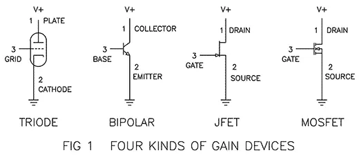
All of these examples have current flowing from pin 1 to pin 2 as a function of the voltage between pin 3 and pin 2. In the example of the tube, the current from Plate to Cathode is largely determined by the voltage between the Grid and the Cathode. The other examples have similar relationships, but vary in the details. We think of pin 3 as the control pin, and signal presented here is amplified to a larger signal passing through the other two pins.
All gain devices have imperfections in their gain. Out of the box you can measure their gain, and for a given test each will have a different value. If you take a single device and measure the gain, you will find that the it varies with the current flowing through the device. It also varies with the voltage across the device as well as the temperature of the device. All three of these will create nonlinear distortion.
Distortion is what you get when the gain is not constant. If the devices had perfectly constant gain under all conditions, they would have no distortion. We are mostly concerned about what happens to an audio signal when it is amplified by a device whose gain figure is changing in response to the signal. The signal goes in and comes out with a different shape. The gain is not perfectly straight – it is bent, or nonlinear.
An important thing about distortion – when you run a signal through a device which is even
slightly non-linear, you have changed the signal forever. You can use various techniques to
reduce distortion after the fact, but you can’t go back.
The problem is greatly compounded when complex signals consisting of many frequencies all travel through the gain device at the same time, or when a simple signal is passed through a number of nonlinear gain stages in series. Of course you can do both, and as we’ll see later, these can add up to a perfect storm of distortion.
Harmonics
When you amplify a single tone (sine wave) and the gain device distorts it, the output contains the original tone plus a series of harmonic tones which are whole multiples of the original frequency. If the original tone is 1 KHz, then the output will contain 1 KHz plus maybe some 2 KHz (second harmonic), 3 KHz (third harmonic), 4 Khz (fourth harmonic), and so on.
Audio signal alternates between positive and negative values. If the nonlinearity of the transfer curve is symmetric with respect to positive and negative, then the harmonics will be odd – third, fifth, seventh and so on. If the transfer curve is bent non-symmetrically, the harmonics will be even – second, fourth, sixth, etc. Figure 2 shows a sine wave with a high 2nd harmonic content. This variety of distortion is often seen in overdriven tubes operated in single-ended Class A mode.
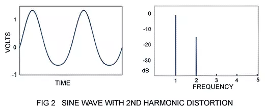
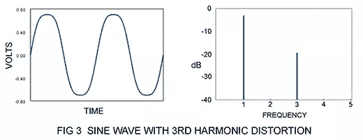
Figure 3 shows a sine wave with a high 3rd harmonic content, recognizable as a “soft” clip, occasionally seen in overdriven push-pull Class A tube circuits.
A gain device’s transfer curve can be expressed as a polynomial: V = a + bX + cX2 + dX3… The “a” term is a DC offset component and the “b” is the linear coefficient, reflecting the distortion-free performance, which would be a straight line. The c, d and etc. are coefficients to a power series representing the “bent” nonlinear portions of the curve.
Similarly, a voltage waveform can be expressed as a sum of harmonic frequencies, each with its own amplitude and phase coefficients. These two ways of looking at things nicely correspond to each other.
Harmonic Distortion and Sound
Many audiophiles believe that 2nd harmonic is to be preferred over 3rd harmonic. Certainly it is simpler in character, and it is well agreed that orders higher than third are more audible and less musical. However when given a choice between the sound of an amplifier whose characteristic is dominantly 2nd harmonic versus 3rd harmonic, a good percentage of listeners choose the 3rd.
I have built many examples of simple 2nd and 3rd harmonic “types” of amplifiers over the last 35 years. When I say “types” I mean that they used simple Class A circuits described as “single-ended” versus “push-pull” and so tended to have a 2nd harmonic versus 3rd harmonic in the character of their distortion, but were not made to deliberately distort.
Anecdotally, it appears that preferences break out roughly into a third of customers liking 2nd harmonic types, a third liking 3rd harmonic, and the remainder liking neither or both. Customers have also been known to change their mind over a period of time.
However the issue is partially obscured by the fact that the 3rd harmonic type amplifiers usually have lower total distortion. Third harmonic usually appears with a negative coefficient, resulting in what we think of as “compressive” – the example in figure 3. It’s worth noting that odd orders on nonlinearity also can be seen altering the amplitude of the fundamental tone -something a distortion analyzer doesn’t ordinarily display.
Audiophiles have been accused of using 2nd or 3rd harmonic distortion as tone controls to deliberately alter the sound. I suppose that there are people who like it that way, but I don’t think this is generally the case. For reasons which will become clearer when we talk about inter-modulation distortion, high levels of any harmonic become problematic with musical material having multiple instruments, and the argument that 2nd or 3rd adds “musicality” doesn’t quite hold up.
The sound of 2nd order type circuits is often praised as “warm” and by comparison 3rd order type circuits are often noted for “dynamic contrast”. 2nd order type amplifiers seem to do particularly well with simple musical material, and 3rd order types generally seem to be better at more complex music. Figure 4 shows a distortion curve of two power stages operated without feedback – the blue is single-ended Class A, the red is a push-pull Class A.
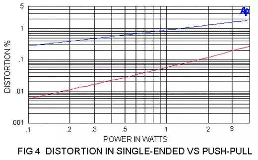
In Figure 4 we see that the 2nd order type declines inversely to the output voltage (the square root of power), and the 3rd order type declines inversely to the square of the voltage (inversely proportional to power). There may be also a relation between this and the perception of “warmth” versus “dynamics”, but it is not clear to me at this time.
Nevertheless, whether you prefer 2nd or 3rd order type amplifiers, let’s agree that we wish to minimize the total amount of distortion. And assuming that we have to put up with some distortion let’s also agree that we prefer 2nd and 3rd harmonic components over 4th, 5th, 6th, 7th and so on.
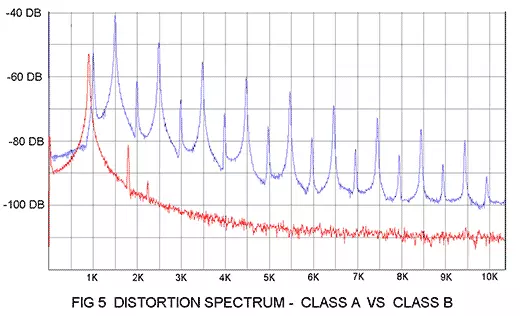
To get lower order harmonic character we want smoother “bends” on the device’s transfer curve. This usually means Class A operation. Figure 5 shows a harmonic comparison between the same push-pull circuit operated Class A versus Class B with a 500 Hz signal. In the case of Class A operation we trade energy efficiency off for a smoother transfer curve, with both halves of the push-pull gain stage smoothly sharing the load and mutually conducting current at all times. In Class B, there is no time when both halves share the load. A popular compromise design, Class AB, smooths the transition out between the two halves by having them both share the load for a portion of the transfer curve.
The high harmonic content of Class B amplifiers brings us to the word monotonicity. Monotonicity describes the relationship between the distortion level and the output level. The smooth transfer curves of Class A amplifiers have a characteristic which is monotonic, that is to say the distortion goes down as the output declines. It implies low order harmonic characteristic, which we have previously agreed is sonically preferred.
If you see a curve with distortion level climbing as the output goes down, it implies crossover distortion caused by the gap between the two push-pull gain elements, and this implies high order harmonics.
The examples of Figure 4 showed distortion declining smoothly with power in Class A amplifiers, but Figure 6 compares a push-pull Class A amplifier (red) with a Class B (blue).
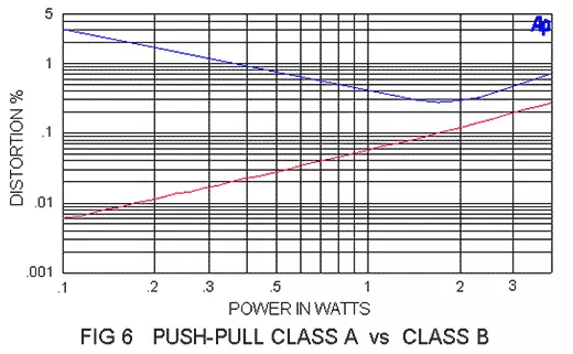
In real life, of course, the distortion of the blue amplifier would likely be reduced through the
use of negative feedback, and the marketing department would be able to say that the
distortion is “less than .05%”. (To avoid any confusion, please note that graphics that you see
in this paper show performance without feedback unless otherwise noted)
Inter-modulation Distortion
If you like to listen to simple music as played by an unaccompanied sackbutt, harmonic
distortion figures might be perfectly relevant to you, but with a lot of music you will find that
inter-modulation distortion becomes the elephant on the dance floor.
Harmonic distortion is closely related to inter-modulation distortion in that both result from the same nonlinear distortion of the gain device, but IM distortion reflects what happens when there is more than one tone involved, and that describes most music. With a single tone, lower order harmonics such as 2nd and 3rd are not as discernible, and in real life most instruments (including vocal) contain a fairly rich set of these harmonics anyway. They are considered musical.
But when two tones are passed through a non-linear device, the amplitude of each of the tones is altered, or modulated by the other tone. The result is a series of “sidebands”, additional tones occurring at the sum and difference of the original frequencies. These additional tones are not generally musically related.
Worse, real music consists of very many tones passing through the nonlinear gain device, and each of these interacts with each of the others. The result will be very complex, and very unmusical.
Figure 7 shows a distortion waveform resulting from two tones passing through a gain stage with both 2nd and 3rd order nonlinearities having 1% coefficients. The two tones have equal amplitude and they are one octave apart. The signal peaks are about 1.8 volts, and the distortion peaks are about .09 volts, or 5%, and the ratio of rms averaged distortion divided by the rms signal is about 4%
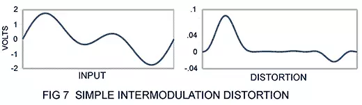
This distortion doesn’t look so bad, but it is obviously higher and more complex than singletone distortion. Let’s see what happens when there are lots of frequencies involved. In Figure 8 we see a waveform consisting of 7 non-harmonically related tones of equal amplitude from 100 Hz to 2800 Hz. If we run this signal through the same gain stage and subtract the original signal we get the distortion seen in Fig 8:
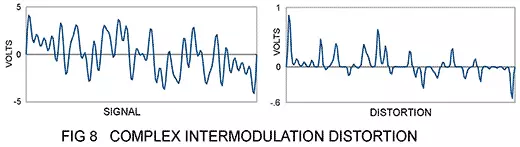
Not very pretty is it? Now the distortion is getting really complex, with lots of harmonics, and the peaks are up around .9 volts. That’s 11 times the .08 volt figure of the single tone, and the ratio of the rms distortion to the rms input signal is about 8%.
My point? IM distortion is the elephant on the dance floor.
Much of the time IM distortion simply forms a complex “noise floor” which masks musical detail. At lower levels, it takes the life out of the music and makes it uninteresting, even irritating. It isn’t as noticeable with very simple music, but it stands out with orchestral material as if the instruments were covered by a veil.
At high distortion levels, the sound simply turns to mud, and we turn it down.
Or off.
Negative Feedback
In 1927 Harold Black invented the negative feedback amplifier in which the output signal of an analog gain circuit is compared with the input signal so as to improve the performance. There are many ways to achieve this effect, all involving negatively amplifying the difference between the input and output so as to minimize this difference.
A simple version can be made from a 3 pin device like the parts from Figure 1, in a circuit that looks like this:
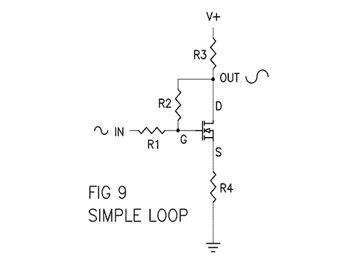
Here we see a single part (Mosfet) in a network of four resistors forming an inverting amplifier with some gain. R3 and R4 set up the “open loop” gain (the gain you get without negative feedback) and R1 and R2 set up a negative feedback loop.
If we remove R2 so that there is no feedback, and assume that the Mosfet is a high gain part, then we would see an “open loop” gain of approximately the ratio R3 / R4. It is not difficult to make R3 / R4 a fairly high figure, giving an open loop gain of maybe 10 times (20 dB) or even 100 times (40 dB) larger than input voltage. A typical example of 100 times would be R3 at a value of 1 Kohm and R4 at 10 ohms.
If you put R2 back in the circuit, you will find the gain reduced. If the ratio of R2 / R1 is much less than the open loop gain, and if the value of R2 is much higher than R3, then the gain of the whole stage becomes quite close to R2 / R1. Examples for this would be R2 at 100 Kohm and R1 at 31.6 Kohm, for an output gain of approximately 3.16 times (10 dB).
Simply put, the difference between the two gain figures is considered the amount of feedback – If the open loop gain is 40 dB and the gain with feedback is 10 dB, then the amount of feedback is 30 dB. In actual audio circuits, the amount of feedback can range between 0 dB (none at all) and as much as 100 dB (100,000 times). Sometimes you don’t need that much, but a typical integrated circuit op-amp comes with that much open loop, so there it is.
Negative feedback is good at reducing all forms of distortion, linear and nonlinear. As a concept, it’s pretty straight-forward: You create one of more gain stages in series in order to get enough gain to equal the final gain figure you want plus the amount of feedback you think you want to use.
As the feedback figure exceeds 20 dB or so, you find that all the measurements will improve by the amount of additional feedback. If the open loop distortion of the amplifier is 5%, then 60 dB of feedback should make it about .005%. It’s relatively easy to construct additional stages or to milk existing stages for more open loop gain, so why not 80 dB for .0005%?
Sounds like something for nothing, doesn’t it?
Not quite. I think it’s a bit more like a credit card – convenient if used wisely, but carrying interest payments and penalties when it’s not.
Negative Feedback and Higher Order Harmonics
Years ago Peter Baxandall pointed out that while negative feedback reduces distortion, it creates additional higher order harmonics in the process. Others have confirmed this phenomenon experimentally and in computer simulations. I found Figure 10 on the internet, attributed to John Linsley-Hood:
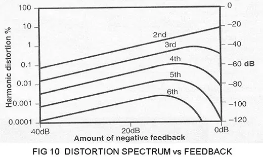
Here we see that as low feedback figures are applied to a single gain stage the 2nd harmonic declines linearly with feedback, but increased amounts of higher order harmonics are created. As feedback increases above about 15 dB or so, all these forms of distortion declining in proportion to increased feedback.
Negative loop feedback creates higher order distortion harmonics, and there seems to be an implication that you might want to use lots of feedback if you plan on using any at all. Some designers look at it this way, others to use feedback sparingly, and some refuse to use it at all.
I performed my own version of the experiment, using a power Mosfet in a single-ended Class A gain stage driving 1 watt into an 8 ohm load:
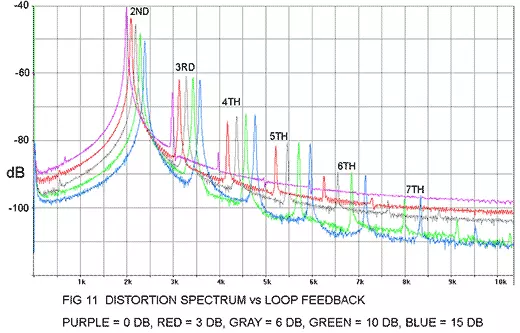
Figure 11 clearly shows the increase in higher order harmonics with the application of negative feedback. In this graphic, the amplitudes are expressed in dB, and the frequency of each curve was slightly offset for clarity.
So it’s pretty clear that while lowering the total amount of distortion, negative feedback does increase the distortion complexity.
Wait! There’s More…
We have seen that distortion complexity results when you pass a simple signal through a gain stage with high order nonlinearities, as in the example of the distortion spectrum of a Class A versus Class B output stage (Figure 5).
We have also seen that distortion complexity results when a complex signal is passed through a gain stage with relatively simple low order non-linearities (Figure 8).
And finally we have seen that distortion complexity is increased whenever you use negative feedback (Figure 11).
I can think of one more source of distortion complexity, that which results from passing a signal through successive gain stages. This is quite common because it is popular to use multiple stages in an amplifier in an effort to generate enough open loop gain so as to have plenty of feedback.
Paradoxically, you can visualize instances of feedback pyramid schemes, in which more gain stages are added to generate more feedback to partially correct for the distortions generated by the additional gain stage.
Figure 12 illustrates the result of cascading multiple stages. Here there are four stages, each having a 1% coefficient of 2nd and 3rd harmonic amplifying a single tone:
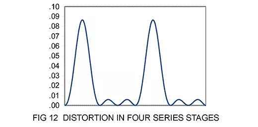
The window of figure 12 represents 1 sinusoidal cycle and you can see the 9th harmonic components at the bottom of the graph. You can also see that much of the distortion is concentrated into large peaks.
You will recall the complex IM example of figure 8 in which seven tones were passed through a single stage. Fig 13 shows what they look like passing them through the four gain stages of figure 12, with the same 1% coefficients for 2nd and 3rd harmonic:
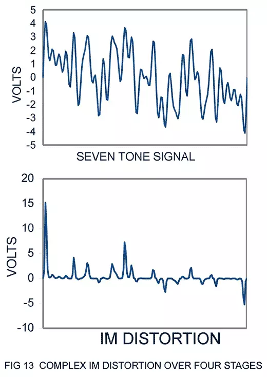
Hmmm. The distortion just keeps getting worse – it might take a lot of feedback to get this down to a reasonable level. The rms value of this distortion is very much lower than the peaks – on the order of 100%. There is approximately as much distortion as original signal.
So now we have four scenarios by which distortion is made more complex, and they can all be experienced with an ordinary audio amplifier. We have seen that these complex distortions can be concentrated into intense peaks, far more powerful than the average values that we might measure with a voltmeter.
Conclusion
Time flies, and there is still much to learn. I haven’t really touched on what these pictures mean to an audiophile, perhaps not what Srajan had in mind when he asked for this piece.
In fact, apart from assuming the preference for low amounts of simple forms of distortion, we haven’t discussed the listener at all. Nevertheless, I am trying to make a point that relates strongly to the apparent disconnect between subjective experience and simple measurements of distortion.
We have seen that nonlinear distortion becomes larger and more complex depending on the nonlinear characteristic of the stages, the number of cascaded stages, and the number of spectral elements in the music.
Negative feedback can reduce the total quantity of distortion, but it adds new components on its own, and tempts the designer to use more cascaded gain stages in search of better numbers, accompanied by greater feedback frequency stability issues.
The resulting complexity creates distortion which is unlike the simple harmonics associated with musical instruments, and we see that these complex waves can gather to create the occasional tsunami of distortion, peaking at values far above those imagined by the distortion specifications.
If you want the peak distortion of the circuit of figure 13 to remain below .1% with a complex signal, then you need to reduce it by a factor of about 3000. 70 dB of feedback would do it, but that does seems like a lot.
By contrast, it appears that if you can make a single stage operate at .01% 2nd harmonic with a single tone without feedback, you could also achieve the .1% peak in the complex IM test.
I like to think the latter would sound better.
© Nelson Pass, 2008