U.S. Patent # 5376899 describes a new amplifying circuit topology that takes advantage of the character of special matched balanced amplifiers that are cross-coupled to provide cancellation of distortion and noise. The result provides high performance with very simple linear circuits, better than previous efforts by an order of magnitude. We have dubbed the approach Super-Symmetry (Su-Sy), an homage to particle physics.
Super-Symmetry works by exploiting the complementary characteristics of precision matched balanced circuits to differentially reject distortion and noise, and extends this symmetry to make the distortion and noise virtually identical on each half of a balanced amplifying circuit. This gives as much as a 100:1 reduction in unwanted signal components without requiring the equivalent amount of negative feedback. It is simply much easier to tweak the two halves of the circuit into symmetry than to eliminate the distortion in each half of the circuit.
To best understand the Su-Sy circuit, we start by considering previous approaches to balanced amplifier design. All three types are composed of a pair of operational amplifiers, where the operational amplifier might be small or large, made of integrated circuits or discrete components, but always having two oppositely phased inputs and and one output. In the first type, two operational amplifiers have their outputs bridged across the load, each has its own independent feedback loop and its own input. Each also has its own distortion characteristic independent of the other amplifier.
In the second type, the negative inputs of the two operational amplifiers share a feedback resistor to form a balanced circuit. This circuit has an advantage in that it can accept balanced and unbalanced inputs, but suffers from the greater distortion and noise since each amplifier reamplifies the distortion and noise of the other. In the third type, the output of a first amplifier is fed back into the negative input of a second amplifier. This circuit does not require and cannot use a balanced input and it suffers from the same increase in distortion as the second type. However, it is commonly employed in conventional amplifiers as a bridging circuit.
The first type gives the best distortion characteristic, being no worse than the performance of a stand-alone amplifier channel. None of these approaches takes any advantage of balanced operation to fundamentally improve the performance of the amplifier itself.
By contrast, the Super-Symmetry topology does not use operational amplifiers as building blocks. It has two negative inputs and two positive outputs and consists of two matched gain blocks coupled at one central point where the voltage is ideally zero. The topology is unique in that at this point, the distortion contributed by each half appears out of phase with the signal, and we use this to reinforce the desired signal and cancel noise and distortion. This occurs mutually between the two halves of the circuit, and the result is signal symmetry with respect to both the voltage and current axis, and anti-symmetry for distortion and noise. This means that the distortion and noise of each half appears identically and cancels.
The diagram on the patent cover sheet shows this topology in its simplest form. Each of the two input devices 20, 21 are driven by an input signal, and their outputs run through a folded cascode formed by devices 30, 31 to develop voltages across current sources 34, 35. The sources 20, 21 are coupled through resistor 40 which is the sole connection between the two halves and which also sets the gain of the circuit.
The gates of the input devices 20, 21 are virtual grounds, and ideally would be at absolutely zero voltage. However, as the gain stage is not perfect, finite distortion and noise voltages appear at these points. These are fed to the other side through resistor 40, and appear in phase at the output of the other half of the system, where they match the distortion and noise of the first half.
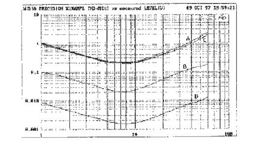
By actual measurement, this circuit does very little to reduce the distortion and noise of each half. Distortion curves before and after the application of Su-Sy are nearly identical. The distortion curves for the circuit shown in the patent cover sheet are: (A) the intrinsic distortion of each half of the real example circuit, (B) the distortion of the differential output lowered due to the intrinsic matching between the circuits, (C) the distortion of each half with Su-Sy applied, and (D) the differential distortion with Su-Sy applied.
With curve (B) we can clearly see that intrinsic symmetry due to the matching of the two halves reduces the distortion by a factor of about 10. Application of Su-Sy (D) creates a more perfect match, and results in an additional reduction by a factor of 10. However there is essentially no difference in the distortion figures at the output (C) of each half of the circuit considered alone. Su-Sy does not work by reducing the distortion per se, rather it works to precisely match the two halves of the circuit and lets the balanced output ignore the unwanted components. As long as the two halves are matched, this performance tends to be frequency independent, and does not deteriorate appreciably over the audio band. With mid-level distortion figures on the order of .002%, this is very high performance for a single balanced gain stage.
Su-Sy is an approach that takes advantage of balanced operation like no other design, and requires a balanced input to retain the precisely matched behaviour. You can drive one input alone, and the circuit will amplify reasonably well, but it will not exhibit the very low distortion character of fully balanced operation.
Su-Sy is ideally used to obtain high quality performance from very simple circuit topologies, avoiding the high order distortion character and feedback instabilities of complex circuits. A single gain stage amplifier using this approach can perform as well as a two or even three gain stage design, and a two gain stage version of this topology can outperform the four or five stages of a conventional amplifier.
The first power amplifier implementing Super-Symmetry is the Pass Labs X1000. It is rated at 1000 watts into 8 ohms. It delivers high quality performance with a single stage Su-Sy front end driving 80 Mosfet power devices used as voltage followers and biased at 600 watts idle dissipation. Early data shows distortion as low as .002% under normal listening levels, and about .1% at 1000 watts. The damping factor is about 1000.
This performance is accomplished with only the two gain stages, an approach previously reserved for low power single-ended Class A designs. By contrast, other high power amplifier offerings in the market use as many as nine gain stages, and still offer less power than the X1000.
Why is this approach important? Because there is a different character of sound attributed to simple linear circuit topologies versus the complex circuits that obtain their performance through the generous use of feedback. It is difficult to produce high power amplifiers with simple circuits, and previous efforts have often been described as powerful and dynamic but musically sterile. Super-Symmetry makes it easy to produce high power amplifiers with the musical characteristic of simple low power amplifiers. It allows elimination of frequency compensation and blocking capacitors and DC servos and regulated supplies and other design band-aids.
Where a thousand watts is not enough, the superb stability of the Su-Sy circuit allows direct coupled output operation in series/parallel arrays up into the territory of 16,000 watts and beyond, retaining the sonic character of a single amplifier, but with massively more voltage and current.